A Superior Alternative to the 4-Point Probe Technique
Non-Contact Non-Destructive Eddy-Current Based MeasurementA Superior Alternative to the 4-Point Probe Technique
Non-Contact, Non-Destructive Eddy-Current Based Measurement
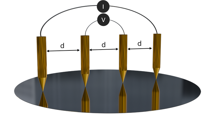
Our eddy-current-based measurement technology offers a powerful, non-contact, and non-destructive solution for both layer thickness and sheet resistance measurements. Unlike the traditional 4-point probe technique, which requires physical contact and may risk damage to delicate surfaces, our non-contact eddy-current approach preserves material integrity by eliminating any physical contact during the measurement process. This non-destructive method not only ensures the longevity of sensitive materials but also provides faster, repeatable results across various applications.
Non-Contact Non-Destructive
For both layer thickness measurement and sheet resistance or resistivity analysis, the eddy-current based technique delivers unmatched precision, efficiency, and durability compared to the 4-point probe. By avoiding surface damage and offering consistent, high-accuracy results, our non-contact, non-destructive measurement technology is the ideal choice for quality control and production environments where both accuracy and material preservation are paramount.
Interaction with a Material
Induced Currents and Heating:
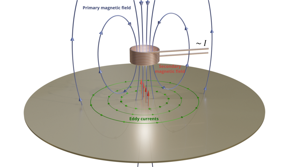
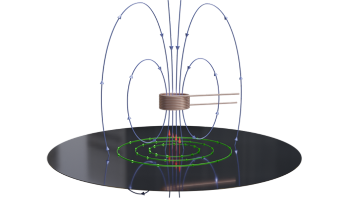
The eddy currents generated in the material flow in closed loops, and their flow is impeded by the material’s electrical resistance. This opposition converts some of the electrical energy into heat (Joule heating).
Opposition to Primary Field:
The eddy currents create their own magnetic field, which opposes the original magnetic field from the coil (Lenz’s Law). This opposition affects the impedance (Z) of the coil.
Non-Contact Non-Destructive.
Measuring Electrical Resistance
Impedance Changes:
The presence of eddy currents alters the impedance of the coil in a manner that depends on the properties of the material, including its electrical resistance. By measuring changes in the coil’s impedance, you can infer properties of the material.
Practical Interpretation
- High Frequency (f): Increases the resistive part R and decreases the penetration depth δ.
- High Conductivity (σ): Decreases the resistive part R and the penetration depth δ.
- High Permeability (μ): Increases the resistive part R and decreases the penetration depth δ.
Lenz’s Law
Lenz’s Law states that the direction of the induced current (and EMF) will be such that it opposes the change in magnetic flux that produced it. This is incorporated in the negative sign in Faraday’s Law.
Impedance Change
The change in impedance (Z) of the coil due to the presence of the material can be approximated using complex impedance models, but a simplified relation for practical purposes can be given by:
Z=R+iX
where:
– R is the resistive part, which is related to the energy loss due to eddy currents (and hence the material’s resistance).
– X is the reactive part, which is related to the inductive effects.
The resistive part R can be related to the material properties and the penetration depth as follows:![]()
With the penetration depth from above, we get:

Non-contact eddy current based measurement arrangement.
We are here to help!
Information you provide in the form is used and stored to process your enquiry and, if you have allowed the cookies, to improve content personalisation.
SWS-Tec processes personal information responsibly. For more information, please review our Privacy Policy (General Data Protection Regulation/GDPR).
* Mandatory field
Office
D-85643 Steinhoering, Germany
Hours
M-F: 9am – 5pm
S-S: Closed

